Web3 Pi: Hardware Assembly
This assembly guide is primarily aimed at assembling the components included in the Welcome Box, but will also be useful for anyone assembling their own hardware.
Info
To avoid errors during the first setup, please follow the instructions precisely.
Please also see the video instructions for more information.
If you have a Welcome Box, unpack the contents and check them against the components listed here.
Components Overview
- Aluminium Top Cover with Screw Points
- Aluminium Case
- Cooling Fins and Exhaust Vent
- Fan Port Access
- POE HAT Connection
- GPIO Access
- MIPI Ports Access
- 30mm PWM Blower-type Fan
- UART Connector
- RTC Battery Connector Access
- PCIe Port Access
- PCIE Film Strip
- Power Button and LED Light
- THRML M.2 Heatsink
- M.2 NVMe Drive Socket

Some parts are in two zipper bags. Open them and carefully pour out the contents. You will find:
- Screws (two types)
- Rubber feet
- Two ribbon cables. You need one, the other one is a spare
Assembly Instructions
1. Prepare the Raspberry Pi 5
Place the thermal pads on the CPU, RP1, RAM and PMIC Chip of the RPi 5.
There are different versions of this case on the market: * If you have four thermal pads, place them in the areas marked in blue. * If you have two thermal pads in the set, place them on the CPU and PMIC (left corner, near the USB-C connector).

2. Connect the Fan
Connect the NEO 5 fan to the RPi 5 fan connector as shown in the image. Please pay attention to how the cable is routed.

Note
There may be a small plug inserted in the fan connector. Remove it.

3. Connect PCIe Ribbon Cable
Connect the PCIe flat ribbon cable to the Raspberry Pi 5 PCIe port. Be careful when handling brown PCIe flip/cover. Pull up the brown flip to release the lock.

4. Place Raspberry Pi in the Case
Drop in the RPi 5 inside the Argon NEO 5 M.2 NVMe Case
Warning
After inserting and pressing the RPi 5 into the central part of the Argon Neo 5 case, they will adhere due to the stickiness of the thermal pads. To ensure good thermal conductivity, do this once and avoid removing the RPi 5 from this part of the case again.

5. Route the PCIe Cable
The PCIe flat ribbon cable should be threaded through the hole in the case, as shown in the picture.


6. Connect PCIe Cable to M.2 Board
Carefully connect the Raspberry Pi 5 with the PCIe flat ribbon cable with copper facing up to the Argon NEO 5 M.2 NVMe Carrier Board Case. Flip up the cover on the M.2 NVMe Expansion Board.

7. Insert MicroSD Card
Here we want you to insert the PREVIOUSLY flashed microSD card with Web3 Pi image.

8. Prepare M.2 NVMe Drive Installation
Connect your M.2 NVMe Drive to the Argon NEO 5 M.2 NVMe Carrier Board. Detailed instructions for this process are described in the following steps.

9. Check NVMe Compatibility
Connect your M.2 NVMe Drive to the Argon NEO 5 M.2 NVMe Carrier Board. Detailed instructions for this process are described in the following steps.
This Board will accept M.2 Key M and M.2 Key B+M NVMe Storage Drive.
Warning
This Board will accept M.2 Key M and M.2 Key B+M NVMe Storage Drive.

10. Remove Heatsink Cover
Remove the "THRMK M.2 Heatsink" cover by unscrewing the four screws at its corners.

11. Adjust Screw Mount Position
Move the screw point on the Board to the appropriate size of your Storage Drive.

12. Insert NVMe Drive
Insert the NVMe drive into the M.2 slot as shown in the picture.

13. Secure the NVMe Drive
Screw in the NVMe drive as shown in the picture.

14. Apply Thermal Pad
Mount the thermal pad on the NVMe drive. There is no need to shorten it. Remember to remove the protective film from both sides.

15. Mount Metal Cover
Mount the metal cover and screw it in using four screws with conical heads.

16. Secure Top Cover
Secure the Aluminium Top Cover with 2 screws.

LCD Display Option
If you have a plastic cover with an LCD display, connect it according to the diagram instead of the original metal one.

Warning
Pay attention to the positioning of the cables when mounting the cover to ensure they don't mechanically obstruct the fan blades.

Final Assembly
The final result should look like this:
Note
Pay attention to the positioning of the cables when mounting the cover to ensure they don't mechanically obstruct the fan blades.

Hardware Connections
Once you have assembled your device, connect the Raspberry Pi as shown below:
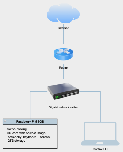
Refer to the following images to verify your setup. These show two typical configurations:
- With a USB drive:

- With an NVMe drive:

Ensure all cables and storage devices are securely connected before proceeding.
Note
Before you connect power, make sure that the ethernet cable is connected with DHCP. Internet connection is required during the installation process.